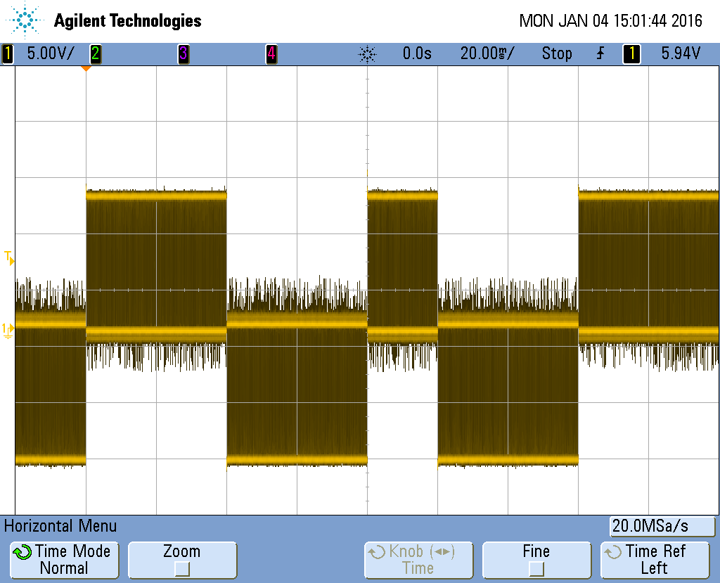
Hello, I am running a S20STH30-0604A stepper motor with the A4988 Stepper Motor Driver interfaced with an Arduino Nano. I have several of these so this is happening on more than one device. I am running the motor continuously in full step mode. It seems as though every 20th step input results in the motor producing a half step output. There is no load on the motor and it runs fine other than that. I have captured a scope image of the motor winding when this happens. Clocking the step input at 50Hz and a 50% duty cycle, I can see the half step occur every 1.5 seconds. Please help if you have experienced anything like this.
What are you measuring with the oscilloscope? Could you post your scope capture and also pictures that show how you have connected your test circuit (including the oscilloscope probes)? Have you measured the signal being sent from the Arduino to the step pin using your oscilloscope to see if it looks good? Are you doing anything with the enable pin?
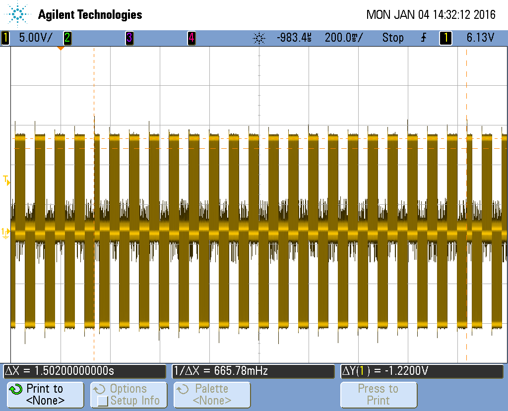
Also, it sound like you might be using some incorrect phrasing in your question. You mention sending pulses at 50hz, so in full-step mode, that is 75 steps in 1.5 seconds, not 20. Each pulse sent to the step pin (in full-step mode) results in the motor taking a full step and there are 4 full steps in the sequence of current switching before the motor coils return to a “home position” (which is not a unique position of the rotor, but a state of current flow through the coils). Microstepping (like half-stepping) creates additional, intermediate states of current flow through the coil.
Hi Nathan,
I have had no luck in trying to insert or attach the scope image with this text editor. I have the scope isolated from earth ground so I am seeing the voltage drop across one of the motor coils. Unfortunately with this configuration I cannot see the “Step” signal from the Arduino. So I really don’t know at what or how many “Step” transitions that this is occurring. I have looked at the “Step” signal and it seems fine. I have even tried disconnecting the “Step” signal from the Arduino and driving it with a pulse generator, and I can see the same “half step”, lets say every 20th motor phase. This seems to be coming from the A4988 Stepper Motor driver.
I will try again to attach images.
Thanks,
George
From the figures you attached, it looks like the driver might be returning to its “home” position every 75 steps; what happens if you change the step rate (say, to 25 Hz)? You can find more information about the “home” position in Figure 9 and Table 2 of the A4988 datasheet. Returning to the home position generally occurs when the driver is reset , though there are several things that can cause a reset.
How do you have the RESET, SLEEP, and VDD pins of the driver connected? Our carrier board pulls the SLEEP pin HIGH (via VDD), so RESET can be connected to the SLEEP pin to pull it HIGH as well. If you have already done this to the RESET pin, you might try connecting both pins directly to VDD to see if the behavior changes.
A reset can also be triggered by the chip overheating, though given the regularity with which your issue is occurring, that seems unlikely to be the cause here. What have you set the current limit of the driver to?
Hi Nathan,
Thanks for the feedback. The “Sleep” and “Reset” pins are connected to the Arduino Nano. VDD is connected to the Arduino’s +5V output. Maybe the +5v regulator from the Arduino is unable to power the logic for both drivers. I will try hard wiring the “Sleep” and “Reset” pins and use another supply for VDD. I will let you know the results.
George
Hi Nathan,
I believe I have solved the problem. I was using the +5V output from the Arduino Nano for the VDD logic supply to the two A4988 driver boards. I don’t think this supply output is enough to run both boards. I have a +5V linear regulator supply for the laser. I connected “Reset”, “Sleep” and VDD to this, and the problem disappeared. I have now reconnected “Reset” and “Sleep” back to the Arduino and keeping VDD as is. And everything is working fine. Very strange how repetitive and periodic this problem was. Starving logic has some weird effects. Thanks again for the clues and help.
George
I am glad to hear you got it working. The current draw for the logic on the A4988 boards is relatively small (a few 10’s of milliamps), but perhaps there is something else in your system that is drawing current at that interval and dropping the voltage on your other 5V supply. You might also check for poor connections in your circuit.