[Solved]PWM Not working in VNH2SP30 Motor Driver

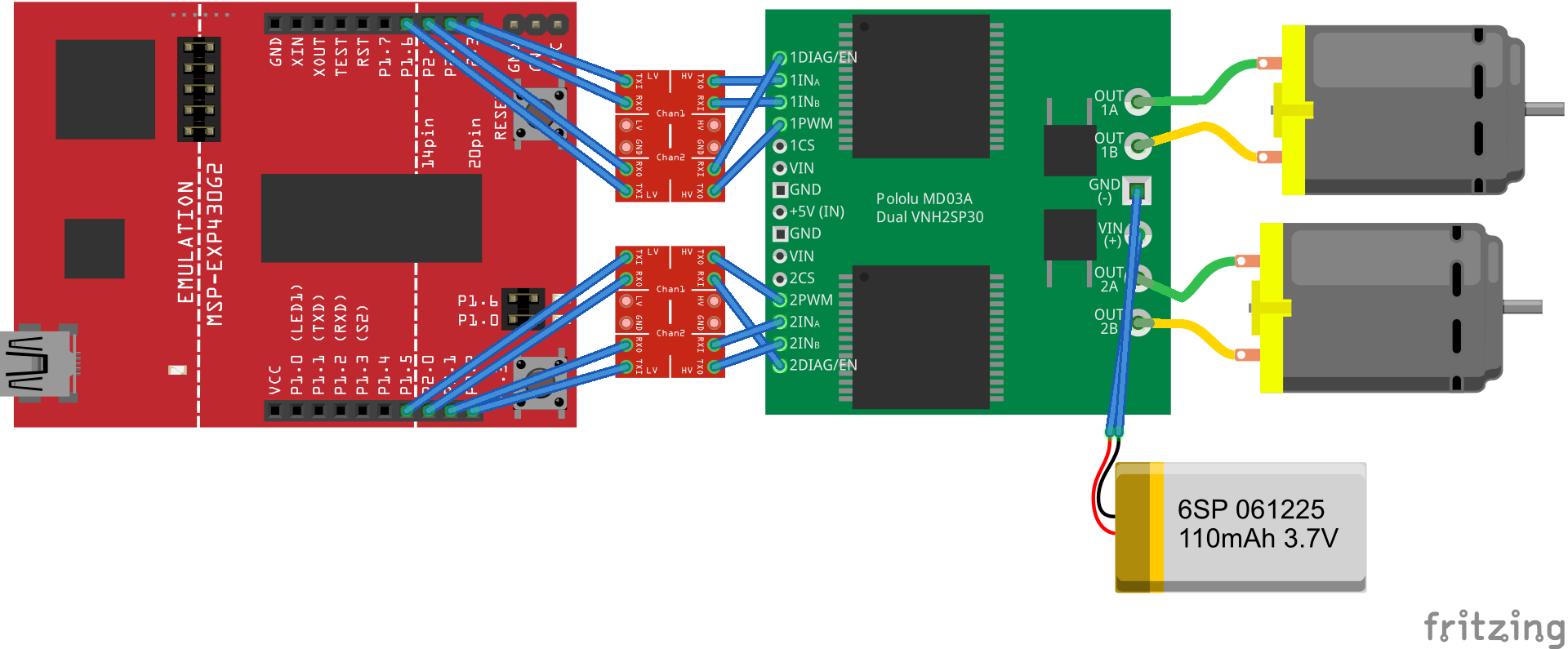
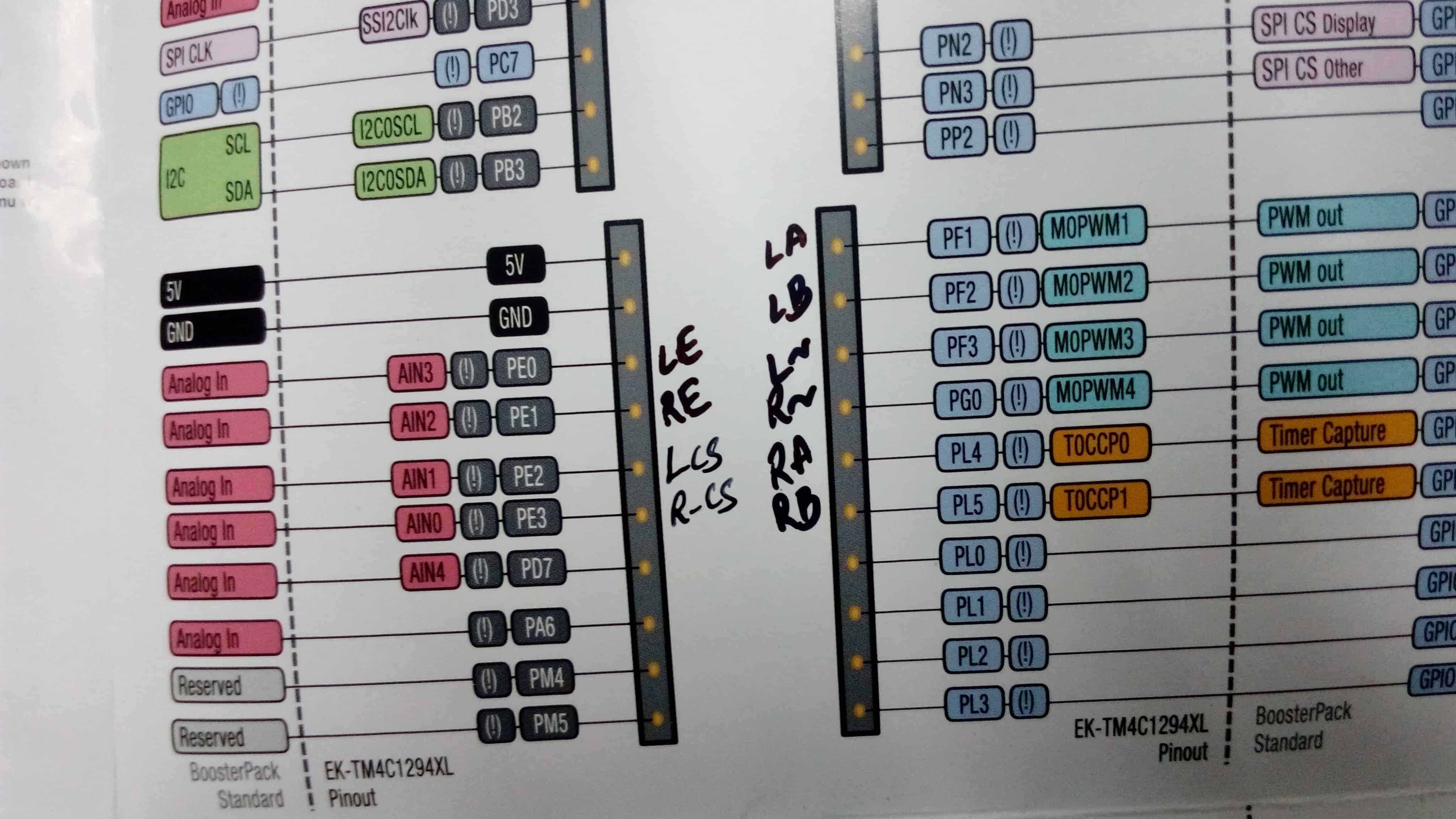
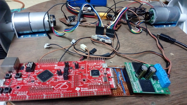
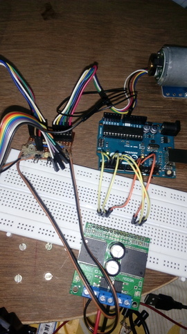
I am trying to run two Pololu 50:1 Motors (https://www.pololu.com/product/1444) with the VNH2SP30 Motor Driver (https://www.pololu.com/product/708/blog) using the Tiva T4MC1294 Connected Launchpad. I have also tried with Arduino UNO and have encountered the same set of problems in both boards.

The problems I am facing are:
[ul]1. Motors are not moving when I supply a PWM signal to the pwm pin of the motor driver using analogWrite() from the pwm compatible pins in arduino. In this case, I have supplied a HIGH voltage to the ENABLE Pin. The LED is flashing once when I give the Motor Signal to the A and B pins. There is a slight jerk of the motor but it does not move anymore.[/ul]
[ul]2. Motors are working when I supply a PWM signal to the ENABLE pin of the motor driver while I have supplied HIGH(5V) to the PWM pin. However, in this case, only one of the motor’s speed is changing with the PWM while the other motor is moving with constant speed. The LEDs are indicating as it should.
[/ul]
[ul]The range of speed variation of the motors with PWM supplied is very poor. The motor which is showing variation in speed is not showing uniformly. I have constantly decreased the duty cycle of the PWM in intervals of 5 seconds. The motor’s speed remains constant initially then it suddenly slows down and comes to a rest even when the duty cycle is above 15%.[/ul]

I do not have access to an oscilloscope so I can’t check the PWM but I used a multimeter to check the voltages and current draw of the motors. The voltage used to run the motors is 11.5v (from LiPo battery) and current draw is about 1.5A.

IMPORTANT UPDATE!!:
I supplied signal to the INA1 and INA2 pins from the microcontroller instead of wireless and it started working. Previously, the battery of my wireless was running low that is why the motors were not moving.
But still, I haven’t been able to control the speed of the motors yet although I am supplying a PWM in the PWM pins and high and low signals in INA and INB respectively. I also found that the motors are moving even when the ENABLE pins are low, contrary to what the datasheet says. The motors are moving only with INA and INB signals only. It does not take into account the signals at ENABLE and PWM pins.

From your description, it sounds like you might not be doing anything with the INA and INB pins in case 1. These pins control the direction of the motor, and the PWM pin controls the speed. You can see more information about this in the truth table on page 14 of the VNH2SP30 motor driver datasheet, located in the “Resources” tab of the Dual VNH2SP30 Motor Driver Carrier’s product page.

If you try controlling the INA and INB pins as described in the datasheet and still have problems, can you post pictures showing all of your connections, as well as a wiring diagram?

-Brandon

Please note the following:

[ul]I am using the T4MC1294XL Connected Launchpad instead of the MSP as shown in the diagram[/ul]
[ul]I am using a LiPo 3-cell (11.1v) battery to power the motors.[/ul]
[ul]I have supplied 5V and GND to the motor driver from a 5V output in the connected launchpad.[/ul]
[ul]I have connected the current sense to the analog input pins of the launchpad.[/ul]
[ul]The red and black wires of the ribbon cable of the pololu motors have been connected to the motor driver[/ul]

Fritzing diagram


Pin diagram


Actual hardware

This is the code I am using. The two motors should rotate at different speeds using this but it is moving at the same speed.

[code]#include <wiring_analog.c>

void setup()
{

Serial.begin(9600);
Serial.println("Serial Terminal started");
pinMode(PF_1,OUTPUT);
pinMode(PF_2,OUTPUT);
pinMode(PF_3,OUTPUT);
pinMode(PG_0,OUTPUT);
pinMode(PL_4,OUTPUT);
pinMode(PL_5,OUTPUT);
pinMode(PE_0,INPUT_PULLUP);
pinMode(PE_1,INPUT_PULLUP);

}

// the loop routine runs over and over again forever:
void loop()
{
//INA and INB setting
digitalWrite(PF_1,HIGH);
digitalWrite(PF_2,LOW);
digitalWrite(PL_4,HIGH);
digitalWrite(PL_5,LOW);

//Uncomment to pull enable low
//digitalWrite(PE_0,LOW);
//digitalWrite(PE_1,LOW);

if(digitalRead(PE_0)==LOW)
Serial.println("Left Motor driver fault");
else
Serial.println("Left motor OK");
if(digitalRead(PE_1)==LOW)
Serial.println("Right Motor driver fault");
else
Serial.println("Right motor OK");

analogWrite(PF_3,100);
analogWrite(PG_0,200);

}[/code]
I have also tried these connections with Arduino and have encountered the same problems.

Thank you for the update.

Do you have access to an oscilloscope that you can use to look at the signals being sent to the driver to make sure they match what you expect? If not, could you try using a multimeter to measure the voltage at the motor output terminals. It looks you are using level shifters between the microcontroller board and the VNH2SP30. Your wiring diagram does not show the high and low reference voltages being supplied, and I cannot tell if you have them in the picture of your actual setup. You might also double check that you have a good common ground between all of the devices.

-Brandon

I have common ground and the voltage references of the logic shifter are connected properly. Hv is connected to 5v and lv to 3.3v from the launchpad pins.
I couldn’t show it in the diagram to avoid congestion.
I don’t have an oscilloscope currently and I am trying to arrange one.
In the meantime, I checked with my multimeter the voltage at the pwm pin is 3.3v. Sometimes it is 2.67v but not lower than that even when the duty cycle is just 10%.
I had a feeling that the problem is with the pwm generation of the launchpad so I checked the motor driver with an Arduino UNO. With arduino, I didn’t need logic level shifters but the problem remained the same and motors speed was not changing.

A digital multimeter will not be able to measure a PWM signal accurately or reliably; however, I agree that it sounds like a problem with the signals being received. I am not familiar with the launchpad board you are using, so it is difficult for me to say what the problem might be. If you could switch your setup back to the Arduino Uno and post the code you are trying with it, I can take a look and see if I notice any problems.

-Brandon

I connected using an Arduino exactly as kas connected in this link : http://forum.arduino.cc/index.php?topic=8652.0

I got correct results once before and the motor’s speed was changing as desired and everything was working correctly.

But suddenly today, it is not working,
Now, when I run the previous code, the motors are not working but when I supply HIGH to either of the Enable Pins EN1/EN2, both motors start moving at full speed.

Sorry, I did not connect the power to the VNH2SP30 motor driver.
It is working fine now.

Thank you a lot for your help!!

I faced another problem now. The PWM, encoder and everything is working perfectly when I am not using the ENABLE/DIAG Pin as I mentioned above.
But, when I used the library of Pololu (https://github.com/pololu/dual-vnh5019-motor-shield) and wrote the code, I get a M1 Fault. I tweaked the condition and checked, there is no M2 Fault, only M1 Fault.
For the encoder, I used this library: http://www.pjrc.com/teensy/td_libs_Encoder.html

[code]
//#define ENCODER_OPTIMIZE_INTERRUPTS
#include <Encoder.h>
#include <DualVNH5019MotorShield.h>

#define COUNTS_PER_REV 1200*2
//As per Pololu website 1200 ticks is to one revolution of motor shaft but experiments shows 2400

//Left Motor Pin Definitions

#define ENDIAG1 1
#define InA1 8
#define InB1 7
#define PWM1 9
#define CS1 A0
#define encA1 5
#define encB1 3

//Right Motor Pin Definitions

#define ENDIAG2 6
#define InA2 11
#define InB2 12
#define PWM2 10
#define CS2 A1
#define encA2 4
#define encB2 2

DualVNH5019MotorShield md(InA1,InB1,ENDIAG1,CS1,InA2,InB2,ENDIAG2,CS2);
Encoder en1(encA1,encB1);
Encoder en2(encA2,encB2);
int enc1_rpm,enc2_rpm;

void setup() {
md.init();

Serial.begin(115200);
Serial.println("Motor Driver and Encoder Test \n --------------------------");

}
void stopIfFault()
{
if (md.getM1Fault())
{
Serial.println(“M1 fault”);
while(1);
}
if (md.getM2Fault())
{
Serial.println(“M2 fault”);
while(1);
}
}

void loop() {
// put your main code here, to run repeatedly:

stopIfFault(); //Without this line, the code is working correctly.
md.setSpeeds(200,10);

if (en1.read()>COUNTS_PER_REV|| en1.read()<-COUNTS_PER_REV)
{
//1 Revoultion complete
enc1_rpm++;
Serial.print("Left Motor(Revs): ");
Serial.print(enc1_rpm);

if (en1.read()<0)
Serial.print(" anti-clockwise");
else
Serial.print("clockwise");

en1.write(0);

Serial.println();

}

if (en2.read()>COUNTS_PER_REV|| en2.read()<-COUNTS_PER_REV)
{
//1 Revoultion complete
enc2_rpm++;
Serial.print("\t Right Motor(Revs): ");
Serial.print(enc2_rpm);

if (en2.read()<0)
Serial.print(" anti-clockwise");
else
Serial.print("clockwise");

en2.write(0);

Serial.println();

}

}[/code]

I figured it out. The Pin Number 1 is used for RX/TX of Arduino and serial comm with computer and enable does not work simultaneously.
I did not use the Pin0 and Pin1 of Arduino and it was working perfectly.

Thanks again.

I am glad you were able to figure out what the problem was and solve it. Thank you for letting us know.

Good luck with your project!

-Brandon