
Hi,
I’m designing an enclosure in OpenSCAD for a robot project, which I will get 3D printed. I want the enclosure to hold two pololu micrometal gearmotors, but unfortunately the design doesn’t suit using the pololu brackets.
Does anyone by any chance have an OpenSCAD file for a holder/bracket for these motors? (I did find the step file, but wasn’t able to make use of that).
If not I’ll get the calipers out and figure it out!
Thanks,
Dan
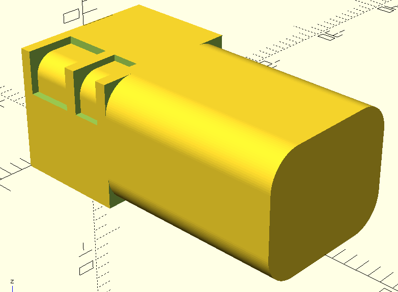
Ok … I just sketched up some OpenSCAD code for this and figured I’d post it here in case it’s useful to someone else. Also feel free to suggest any improvements/fixes.
I would recommend just using the pololu brackets if your design supports that!
Regards,
Dan
//------------------------------------------------------------------------------------
// OpenSCAD code to allow mounting of a polulu micro-metal gearmotor.
//
// The main module is pmm_gearmotor_hole.
// This can be used with difference() to leave a hole where a pololu micro-metal gearmotor
// would fit.  Of course you would need to split what is left behind into two halves somehow
// (vertically or horizontally), so the motor could actually be inserted.  Then those two halves
// could be joined together somehow, eg with screws and nuts.
//
// This allows for a specified 'gap' all the way around, which likely depends on the
// accuracy of the 3D printer used.
//
// NOTE: this hasn't been tested yet and likely needs fixes/tweaks following a 3D print test.

//------------------------------------------------------------------------------------
// Cuts out a curved section:

module pmm_cutout(diameter, width, depth, height, offset, gap, fn) {

    difference() {
        translate([-width, 0, -height])
            cube([width + gap, depth, height + gap]);

        x_center = -offset - diameter / 2;
        y_center = -offset - diameter / 2;
        depth2 = depth + 2 * gap;

        translate([x_center, -gap, y_center])
            rotate([-90, 0, 0])
            cylinder(d = diameter, h = depth2, $fn = fn);

        translate([-width-gap, -gap, -height-gap])
            cube([width - offset + gap, depth2, height - offset - diameter/2 + gap]);

        translate([-width-gap, -gap, -height-gap])
            cube([width - offset - diameter/2 + gap, depth2, height - offset + gap]);
    }
}

//------------------------------------------------------------------------------------
// Creates hole for gearmotor:

module pmm_gearmotor_hole(
    gap=0.2, // the extra tolerance all around the hole.  Also used as an overhang for any part that will be subtracted with difference().
    fn=100   // accuracy of cylinders
    ) {

    frame_width       = 11.9  + 2 * gap;
    frame_height      =  9.9  + 2 * gap;
    frame_depth       =  9.0  + 2 * gap;
    frame_thickness   =  0.75 + 2 * gap;     // thickness of brass plates
    frame_void_depth1 =  4.2  - 2 * gap;     // depth of wider void with gears, closer to shaft
    frame_void_depth2 = frame_depth - frame_void_depth1 - (3 * frame_thickness); // depth of narrower void with gears, closer to motor

    spacer_diameter1  = 3.0 + 2 * gap;       // diameter of narrower brass spacers, closer to shaft
    spacer_diameter2  = 3.2 + 2 * gap;       // diameter of wider brass spacers, closer to motor
    spacer_offset1    = 0.6;                 // distance from edge to narrower brass spacers, closer to shaft
    spacer_offset2    = 0.5;                 // distance from edge to wider brass spacers, closer to
    spacer_width      = 4.0;                 // width of cutout around spacers
    spacer_height     = 3.5;                 // height of cutout around spacers

    motor_depth = 15.25;                     // depth of motor casing
    motor_curvature_diameter = 5.0 + 2 * gap;

    render()
        translate([0, -gap, -gap])
        difference() {

            //--------------------------------------------
            // solid block we start with:

            translate([-frame_width/2, 0, 0])
                cube([frame_width, frame_depth + motor_depth, frame_height]);

            //--------------------------------------------
            // carve away four cutouts for the gear section:

            for (corner = [0 : 1]) {
                side = corner == 0 ? 1 : -1;
                up   = corner == 0 ? 1 : 0;

                translate([side * frame_width/2, frame_thickness, up * frame_height])
                    rotate([0, corner * 180, 0])
                    pmm_cutout(spacer_diameter1, spacer_width, frame_void_depth1, spacer_height, spacer_offset1, gap, fn);

                translate([side * frame_width/2, frame_thickness * 2 + frame_void_depth1, up * frame_height])
                    rotate([0, corner * 180, 0])
                    pmm_cutout(spacer_diameter2, spacer_width, frame_void_depth2, spacer_height, spacer_offset2, gap, fn);
            }

            //--------------------------------------------
            // carve away four cutouts for the motor body:

            for (corner = [0 : 3]) {
                side = corner <= 1 ? 1 : -1;
                up   = (corner == 0 || corner == 3) ? 1 : 0;

                translate([side * frame_width/2, frame_depth, up * frame_height])
                    rotate([0, corner * 90, 0])
                    pmm_cutout(motor_curvature_diameter, motor_curvature_diameter/2, motor_depth + gap, motor_curvature_diameter/2, 0, gap, fn);
        }
    }
}

pmm_gearmotor_hole();Hello, Dan.
Thank you for sharing. Hopefully some of our other customers will find that helpful.
- Grant