Dear: Pololu
You should know that I am using mc33926 product# 1213 motor driver with arduino nano to drive my rover 5. I am using pins 13 - 9 from my arduino nano and here is my code.
[code]const int M2D1PWM = 12;
const int M2D2PWM = 13;
const int M2IN1 = 9;
const int M2IN2 = 11;
const int ENABLE = 10;
void setup() {
// put your setup code here, to run once:
pinMode(M2D1PWM, OUTPUT);
pinMode(M2D2PWM, OUTPUT);
pinMode(M2IN1, OUTPUT);
pinMode(M2IN2, OUTPUT);
pinMode(ENABLE, OUTPUT);
}
void loop() {
// put your main code here, to run repeatedly:
digitalWrite(ENABLE, HIGH);
digitalWrite(M2IN2, HIGH);
digitalWrite(M2IN1, LOW);
analogWrite(M2D2PWM, 180);
analogWrite(M2D1PWM, 180);
}[/code]
What I am trying to ask you is why is the motor driver continuing to do nothing if the code and wiring should be correct. Please help me? Thank you.
From: Noah
Hello, Noah.
I am sorry you are having problems using your dual MC33926 motor driver. I briefly looked at your code, and it looks like you are trying to use analogWrite() with pins that do not support it. You can refer to the Arduino Nano page to see which pins support PWM. Also, as mentioned in the Basic Application Connections section on the Dual MC33926 Motor Driver Carrier product page, you should only apply a PWM signal to one of the disable input pins for speed control and drive the other pin high or low accordingly to enable the outputs.
- Jeremy
Dear: Jermey
You should know I didn’t know which pins were pwm and so thank you. I thought that all digital pins were pwm compatible but apparently I was wrong. Also you should know that I thought the Basic Application Connections page were saying the opposite so thank you. There is just one thing I didn’t get is that you never said which pin I should apply pwm into and which pin to keep low but anyways I just did what the Basic Application Connections said to do.
Just to let you know the motor is still not moving. I noticed absolutely no changes whatsoever. Here is my code and new wiring.
[code]const int M2D1PWM = 6;
const int M2D2PWM = 5;
const int M2IN1 = 9;
const int M2IN2 = 11;
const int ENABLE = 10;
void setup() {
// put your setup code here, to run once:
pinMode(M2D1PWM, OUTPUT);
pinMode(M2D2PWM, OUTPUT);
pinMode(M2IN1, OUTPUT);
pinMode(M2IN2, OUTPUT);
pinMode(ENABLE, OUTPUT);
}
void loop() {
// put your main code here, to run repeatedly:
digitalWrite(ENABLE, HIGH);
digitalWrite(M2IN2, LOW);
digitalWrite(M2IN1, HIGH);
digitalWrite(M2D2PWM, LOW);
analogWrite(M2D1PWM, 180);
}[/code]
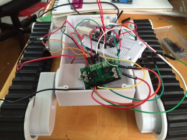
If you are sending a PWM signal to D1, D2 should be driven HIGH to enable the outputs. If you continue to have problems after changing that, could you tell us more about your setup? What are you using for your power supply? Could you post pictures of your setup that clearly show how the wires are connected between the boards?
- Jeremy
Dear: Jermey
Thank you for the reply and I seriously didn’t get any of this from the pololu “Basic Application Connections” but anyways I tried your code and it didn’t work. Nothing happened. You also requested I take a picture that is better of my wiring and I did. OUT1 should be connected to the red wire on the left motor while OUT2 should be connected on ground on the left motor. I am also going to try giving more power into the motor driver just so to see weather or not connecting it to 5v on the arduino nano isn’t good enough. Thank you.
From: Noah
[code]const int M2D1PWM = 6;
const int M2D2PWM = 5;
const int M2IN1 = 9;
const int M2IN2 = 11;
const int ENABLE = 10;
void setup() {
// put your setup code here, to run once:
pinMode(M2D1PWM, OUTPUT);
pinMode(M2D2PWM, OUTPUT);
pinMode(M2IN1, OUTPUT);
pinMode(M2IN2, OUTPUT);
pinMode(ENABLE, OUTPUT);
}
void loop() {
// put your main code here, to run repeatedly:
digitalWrite(ENABLE, HIGH);
digitalWrite(M2IN2, LOW);
digitalWrite(M2IN1, HIGH);
digitalWrite(M2D2PWM, HIGH);
analogWrite(M2D1PWM, 180);
}[/code]
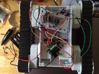
The 5V regulator on the Arduino Nano is probably not appropriate for supplying the current drawn by your motor. Could you try supplying the MC33926 with a separate power supply? In your first picture, I see that you have a 4 AA battery holder, which might work. Could you also post pictures of the other side of the dual MC33926 motor driver so I can inspect the soldering?
- Jeremy
Dear: Jeremy
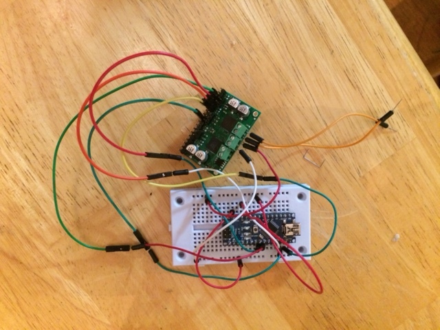
You should know I just did that. I wired 6 volts (4 * AAA batteries) to the motor driver and still nothing happened. Is the board short circuited because if it is I could use my other board. I’d have to solder it though. Also I have been using this board for about two weeks and still nothing has happened. How do I know if it is shorted. Here is a picture of my first soldering.
From: Noah
The soldering between the pins, terminal blocks, and the board look like it is not making good connections, and I do not expect the motor driver to work like that. Could you try retouching the pins with a soldering iron to make sure the pins make good connections with the board? You might find this soldering tutorial helpful.
- Jeremy
Dear: Jeremy and Pololu
Thank you for your help I suppose I didn’t need it. All day today and yesterday I’ve been soldering but I seriously could have done a way better job than what I did. I found a dagu mini driver in my basement which has a built in motor driver which I know how to use and a encoder module inside of it so for the past hour I figured out how to use the rover 5 without the motor driver from you. Thank you for your time and if anybody is curious about how to use the Mc33926 motor driver please read the forum. Thank you.
From: Noah
Thanks for letting us know. If you would like to continue troubleshooting your MC33926 driver in the future, please post updated pictures of the board and setup here.
- Jeremy

